Diodes AHC1724Q and AHC1725Q Hall Sensors Measure EV Charger Current to ±50A
- Nidhi Agarwal
- 585 reads
Diodes’ AHC1724Q and AHC1725Q combine galvanic isolation, 1.2mΩ conductor resistance and 120kHz bandwidth for charger current sensing.
For EV charger designers, current sensing has to fit beside power switching, protection and control circuitry while keeping measurement errors and heat in check. Diodes Incorporated’s AHC1724Q and AHC1725Q Hall effect sensors address that constraint with a low-resistance current path, galvanic isolation and a stated measurement range up to ±50A.

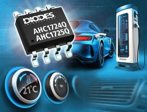
Diodes says the automotive-compliant parts are intended for onboard chargers (OBCs) and charging stations. Their small package footprint is meant to help engineers reduce board area where charger layouts are crowded. The company specifies both AC and DC measurement, with versions for unidirectional or bidirectional current sensing.

Low resistance limits sensor heating
Each device routes the measured current through an integrated copper conductor, while a Hall sensor detects the magnetic field generated by that current. The conductor’s resistance is 1.2 milliohms. That low value limits the voltage drop and power dissipated as heat in the sensing path compared with a higher-resistance shunt approach, although the actual loss still depends on current and operating conditions.

The distinction matters in compact power electronics: a sensor adds its own thermal load to a board that already has switching devices and other heat-producing components. Reducing conduction loss at the measurement point can ease that local burden. The published resistance alone, however, doesn’t establish total system efficiency or the temperature rise in a particular layout; those depend on current profile, copper and thermal design.

The ±50A measurement capability gives the devices a stated range for charger current monitoring. Diodes lists options for sensing current in one direction or both, which lets designers select according to whether their measurement point needs to track charging flow alone or also detect reverse flow. The available information doesn’t identify specific part-to-range pairings, so those details need to be checked against the device documentation during selection.
Isolation and dynamic response
The current-carrying conductor is electrically isolated from the sensing circuit. Diodes specifies a maximum working voltage of 420V DC and says the devices meet the basic insulation requirements of UL 62368-1. The integrated isolation can remove the need for a separate isolation circuit at the sensing interface, potentially saving board area and component count. Designers still need to check the complete system’s insulation coordination and safety requirements against the product documentation and applicable design conditions.

For control and protection loops, the sensor’s response figures are as relevant as its current range. The AHC1724Q and AHC1725Q have a specified bandwidth of 120kHz, a response time of 4.0µs and a propagation delay of 2.0µs. These figures describe different aspects of how quickly the output follows changes in current; they give engineers parameters to assess when checking the sensor against switching behavior, control-loop timing or fault detection needs.

Diodes also describes the sensing architecture as low-offset and chopper-stabilised. Chopper stabilisation is used to reduce offset-related measurement error, which can matter when a system needs to distinguish small current changes from the sensor’s own baseline error. The output voltage varies in proportion to the supply voltage, so the receiving circuit must account for that relationship when setting its signal range and reference.
Use beyond vehicle charging
The company also identifies industrial power supplies, load detection and management, overcurrent fault protection, and HVAC equipment as target applications. These systems share a need to measure current while keeping the signal circuitry electrically separated from the conductor being monitored. The sensors’ stated high-temperature and harsh-condition suitability may broaden where they can be considered, but the supplied specifications don’t give temperature limits or environmental test conditions.
For a design review, the practical checks are the chosen device’s directionality, current range, 420V DC working-voltage limit, insulation needs, signal compatibility and timing requirements. Package dimensions, accuracy limits and detailed operating conditions aren’t included in the available product information here, so they remain key items to confirm in the datasheet. The headline trade-off is clear: a 1.2mΩ integrated path and built-in isolation can simplify a compact sensing channel, while final fit depends on the complete electrical and thermal design.