ArduBot Fits ROS 2 Mapping and Navigation Into a 100 mm Robot
- Ajax
- 416 reads
The 100 × 100 × 50 mm ArduBot combines ToF depth sensing with ROS 2 tools for 2D navigation and 3D mapping.
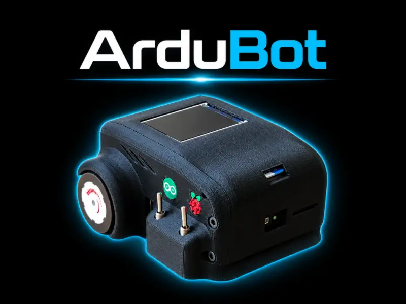
ArduBot’s notable engineering choice is to split a miniature robot’s work between a compact onboard computer and a remote PC. The differential-drive platform measures 100 × 100 × 50 mm, yet its software setup supports 2D mapping and navigation alongside 3D reconstruction. That division lets the robot carry the sensors and motor controls while a host machine runs the heavier mapping and planning tasks.
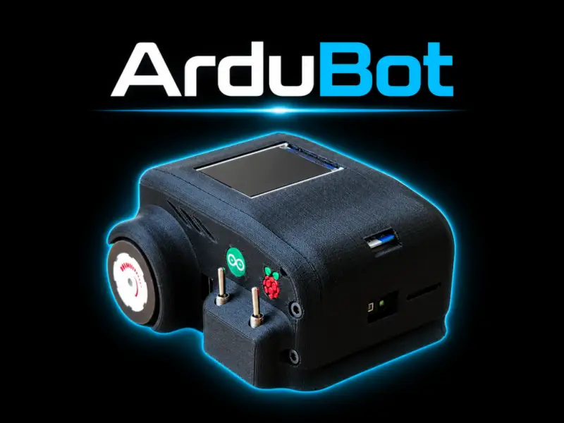
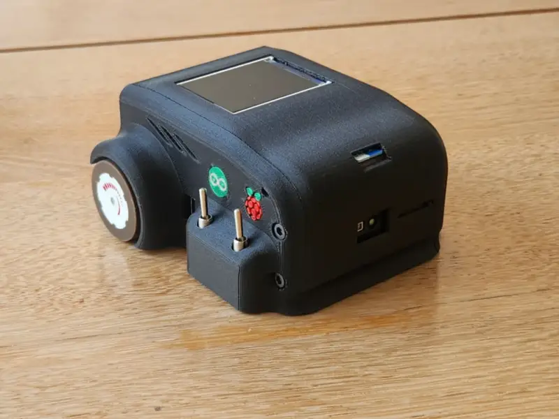
Developed by jled12, ArduBot brings together a Raspberry Pi 4 Model B, an Arduino-based motor-control system, wheel encoders, an IMU and an Arducam time-of-flight (ToF) camera. Its open-source project includes code, circuit diagrams and files for a 3D-printable chassis, giving builders access to both the hardware design and the ROS 2 software arrangement.
A small robot with distributed computing
The Raspberry Pi 4 Model B handles ToF data acquisition and processing, as well as ROS 2 node communication. An Arduino Pro Mini, connected through an Arduino Dagu Magician, takes care of lower-level motor control, wheel-encoder feedback and IMU data collection. An ST7735 TFT display provides status readouts on the chassis.
This split assigns time-sensitive tasks such as motor control to the Arduino while the Pi handles sensor data and communication. The BNO055 IMU and wheel encoders supply orientation and odometry information. Together, those measurements help describe how the robot is moving; the ToF camera adds depth observations of its surroundings.
ArduBot uses ROS 2 Humble and sends telemetry over Wi-Fi. The setup includes ROS 2 domain bridging and Chrony time synchronization between the onboard system and remote PC. Synchronizing clocks matters when software combines measurements from different devices: sensor readings and motion data need usable time references to relate observations to the robot’s movement.
The remote PC runs SLAM Toolbox for 2D grid mapping, Nav2 for path planning and OctoMap for 3D volumetric mapping. RViz provides a way to visualize the results. This architecture keeps demanding mapping and planning computations off the small robot, though it also makes those functions depend on the host computer and the wireless connection.
One depth sensor, two map formats
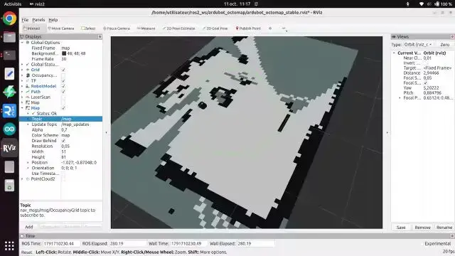
The ToF camera measures depth across its field of view. ArduBot uses those measurements in two different representations. For 2D mapping, depth data is converted into laser-scan-like data that SLAM Toolbox can use to build an occupancy grid. That grid represents the floor plan for Nav2’s navigation work.
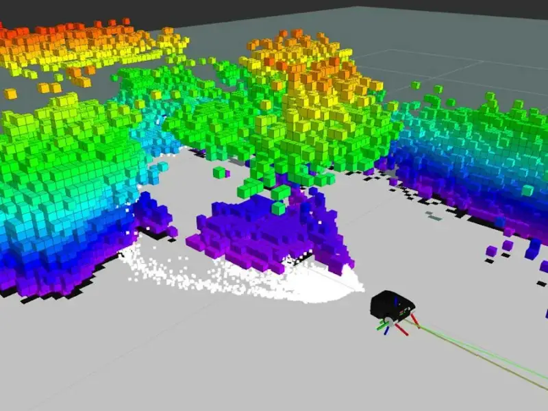
For 3D reconstruction, the camera’s matrix of depth values becomes a point cloud. OctoMap integrates that data into a volumetric model, representing features such as walls, furniture and obstacles at different heights. The distinction is useful: a 2D grid gives navigation software a compact view of traversable space, while a 3D map retains information about the vertical structure of the environment.
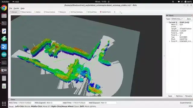
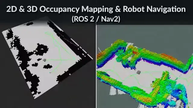
That dual use is the project’s clearest technical point. A single depth sensor can feed both a navigation-oriented map and a richer spatial model, with software converting the measurements to suit each task. The camera’s field of view and depth data therefore shape what the robot can observe, while the remote PC supplies the compute needed to turn those observations into maps.
What the architecture means for builders
ArduBot offers a compact way to work with ROS 2 navigation, depth sensing and 3D mapping in one project. Its size makes the hardware arrangement easy to study as a complete mobile platform, while the split between onboard control and remote computation exposes a practical design trade-off: a small robot can do less processing locally when a connected host is available to run the larger workloads.
That setup also gives builders distinct areas to investigate. The Arduino side covers motor commands and feedback; the Pi handles sensor processing and ROS 2 communication; the PC runs mapping, planning and visualization. Changes to one layer can be explored while keeping the other roles clear. The project’s open design files and software provide a starting point for those experiments, though the supplied details do not specify sensor range, operating speed or mapping accuracy.
Builders can find the project’s code, circuit diagrams and chassis files in the ArduBot-ToF-SLAM GitHub repository. Product details for the Arducam ToF camera are also available. The project is most useful as a working example of how depth measurements, wheel odometry and ROS 2 tools can be connected across a small mobile robot and a remote computer.