Impulse vs Reaction Turbines: Pressure Change, Flow Paths and Operating Range
- Chennu Vinodh Reddy
- 999 reads
Impulse turbines extract energy from high-speed jets; reaction turbines use pressure and velocity changes through a water-filled runner.

The key difference between impulse and reaction turbines is where the water’s pressure energy becomes motion and how that moving water transfers energy to the runner. In an impulse machine, a nozzle forms a high-speed jet before it reaches the runner. In a reaction machine, water enters the runner with pressure energy still available, and both pressure and velocity change as it passes through the blades. That distinction shapes the casing, flow control, installation and typical operating range.
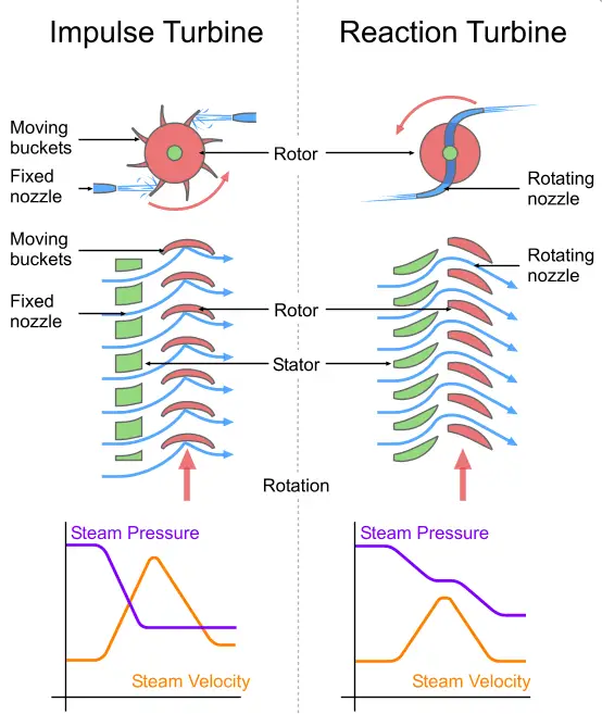
Schematic comparison of an impulse turbine and a reaction turbine. The rotor turns; the stator remains stationary. Image source: Emoscopes (Wikimedia Commons).
Where the energy transfer occurs
An impulse turbine converts the available hydraulic energy into kinetic energy in a nozzle. The resulting jet strikes the runner buckets, and the change in the jet’s momentum turns the wheel. The pressure through the runner remains approximately atmospheric; the runner extracts energy chiefly by redirecting and slowing the water. A Pelton wheel is a familiar example of this arrangement.
A reaction turbine converts only part of the available energy into kinetic energy before the water enters the runner. The remaining pressure change occurs as the water moves through passages between the blades. The fluid acts on the runner through changes in both pressure and velocity, so the runner operates full of water and needs an enclosing, watertight casing.
This distinction is captured by the degree of reaction: it is zero for an ideal impulse turbine, while a reaction turbine has a degree greater than zero and up to one. The value describes how much of the energy transfer is associated with pressure change in the runner. It helps explain the different operating principles, but by itself it does not establish which machine will be more efficient in a particular installation.
Flow paths and machine hardware
Impulse machines admit water as one or more discrete jets. Each jet is directed at buckets around the runner, and a needle valve in the nozzle can regulate flow. The runner does not operate submerged in a full stream: air can reach the buckets, and the casing does not maintain hydraulic pressure. It chiefly contains splashing and directs spent water toward the tail race.
Reaction machines admit water around the runner circumference. Depending on the design, the flow travels through the runner in radial and axial directions. Guide vanes regulate the flow and set its direction as it enters the runner. Other listed components include a scroll casing, a stay ring and a draft tube. Because the passages remain filled, the casing and flow path form part of the machine’s hydraulic operation.
A draft tube is a gradually expanding passage that carries water from a reaction turbine toward the tail race. Reaction turbines are generally connected to the tail race this way, and may be installed above or below it. The arrangement differs from the typical impulse installation, which sits above the tail race and does not use a draft tube.
Choosing between the two types
Impulse turbines are associated with high water heads and low discharge, while reaction turbines are used across low and medium heads and can handle medium or high discharge. These are broad selection guides, not universal limits: the suitable turbine depends on the site’s available head and flow, as well as the machine design. The source comparison names the Pelton wheel as an impulse example, and Francis, Kaplan, propeller, Deriaz and tubular turbines as reaction examples.
Those categories reflect the different ways each type accepts water. A high-head, lower-flow supply can be delivered as a concentrated jet to an impulse runner. Reaction designs use a filled flow path through the machine, making their runner, casing and discharge arrangement part of a continuous hydraulic circuit.
The comparison also characterizes impulse machines as more hydraulically efficient and requiring less maintenance. Those claims need context: efficiency depends on the particular turbine, operating point and installation, while maintenance depends on components, materials, water conditions and service practice. The broad labels alone are not enough to predict performance or upkeep for a specific project.
Practical takeaway
For an initial comparison, focus on the pressure change through the runner, whether water arrives as a jet or fills the blade passages, and how the machine returns water to the tail race. Those features determine whether the design calls for a nozzle and buckets or a watertight casing, guide vanes and usually a draft tube. Matching that architecture to the site’s head and discharge is more useful than treating turbine type as a simple efficiency ranking.