PCB Solder Mask Pencil Hardness Testing: Methods, Endpoints and Reporting
- li
- 621 reads
A useful solder mask hardness result depends on the specified method, cure history and damage endpoint—not just the pencil grade.
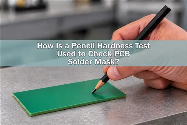
A pencil hardness result for PCB solder mask is meaningful only when the method, coating condition and damage endpoint are recorded with the grade. The test compares resistance to local damage from prepared graphite pencils; it doesn’t measure adhesion, abrasion life, electrical insulation or the hardness of the copper and laminate beneath the mask.
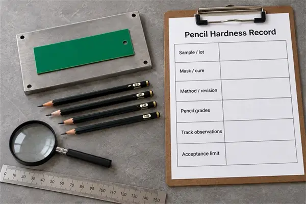
That distinction matters in production. A soft result can flag a change in the cured coating, but it doesn’t identify the cause on its own. Material selection, cure history and test setup all warrant review. Since the test can mark the surface, use an approved coupon or sacrificial area rather than leaving an unexplained track on a deliverable board.
Choose the method before testing
IPC-TM-650 2.4.27.2 specifies a pencil method for solder mask abrasion. ASTM D3363 covers pencil hardness of films, and ISO 15184 addresses paint and varnish films. Their use of pencils doesn’t make the methods interchangeable. The purchase specification should identify the applicable standard and revision, and the inspection must follow that method’s conditions and endpoint.
For example, a drawing that calls for ASTM D3363 requires the conditions and endpoint in that method; an IPC result isn’t a substitute without agreement. Likewise, don’t import a tester’s advertised 750 g load into the IPC procedure as if the standard specified it. Record whether the test was manual or instrumented and document the loading arrangement actually used.
PCB construction can affect the test. Copper topography, mask thickness and support beneath the sample influence local conditions, so a painted metal panel may not represent a patterned board. For HDI boards, narrow mask dams and dense openings can leave too little uninterrupted surface for a valid stroke. An agreed representative coupon is preferable to dragging a pencil across pad edges.
Control the coating’s cure history
Test after the specified final cure and conditioning, not at the tack-dry stage. Use the current process sheet for the actual mask formulation, mixing ratio, coating thickness and cure sequence. An oven setpoint doesn’t tell you the temperature the board experienced: loading and thermal mass affect its heating history.
Keep each sample traceable to its production lot. Record the ink identity and batch, the cure equipment or cycle reference, board-temperature evidence where required, cooling interval and test environment. A separately cured coupon may describe that coupon rather than the production boards.
For FR4 boards, select a representative mask-covered region and support it firmly. Metal-core boards have a different construction, so don’t assume the same oven setting produces the same board heating history. This is a question of curing the coating, not measuring the hardness of the metal core.
Don’t extend the bake repeatedly just to obtain a passing pencil grade. Extra heat can affect other mask properties and later processing. If under-cure is suspected, review the approved process window in a controlled way before considering rework.
Read the grades as an ordered scale
The pencil series runs from softer B grades through HB and F to harder H grades. Within the B series, larger numbers indicate softer pencils; within the H series, larger numbers indicate harder ones. So 2B is softer than HB, while 3H is harder than H. The grades are ordered categories, not equal numerical steps: a 6H result doesn’t mean a coating is twice as hard as one rated 3H.
F is its own grade and shouldn’t be substituted with HB or H. Pencil manufacturer and batch can also affect comparisons. Use a consistent, suitable set for routine checks and agree on the set when resolving differences between laboratories. The graphite core is often called pencil lead, but it contains no metallic lead.
Prepare the pencil and board consistently
A suitable setup includes graded pencils, tools for preparing the tips, firm sample support and enough light to examine the track. A guide or tester can control geometry, but its fixture must match the selected method. A sharp writing point isn’t suitable when the procedure requires a flat end.
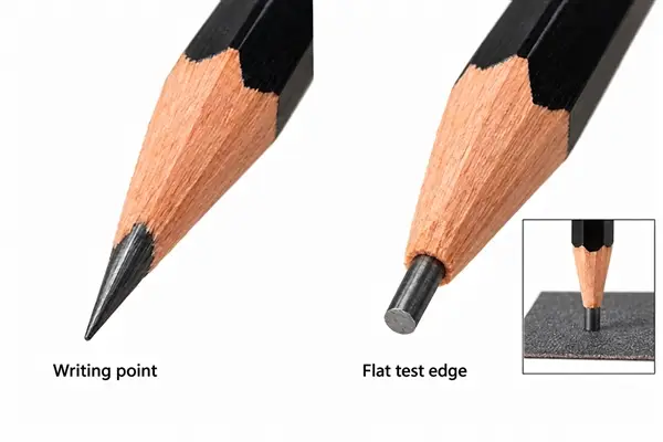
Expose and prepare the graphite as the method directs. Flatten the end square to the pencil axis, and check for chips or a rounded edge. Reprepare a damaged or worn tip; loose abrasive particles can also contaminate the mask and leave a misleading mark.
Choose a clean, level area away from holes, exposed pads, legend ink and existing damage. Record whether the test area lies over copper or laminate, since film thickness and support may differ between those locations.
Apply the specified stroke and endpoint
For the IPC solder mask pencil method, place the coated sample on a firm, horizontal support. Start with the hardest pencil in the specified series, hold it at 45 degrees and push away with consistent downward and forward pressure over the specified 6.4 mm stroke. Examine the track, then move to softer grades until the coating is no longer cut or gouged. Record the hardest grade that does not cut or gouge, along with the method and observations.
Keep each track separate from earlier damage and recheck tip preparation if marks are irregular. Use the repetition and acceptance rules in the approved inspection instruction; there is no universal sample count. If the specification calls for an instrumented ASTM or ISO procedure, follow it as written instead of combining parts of different methods.
Separate graphite transfer from coating damage
A dark line may be transferred graphite on an intact film. Examine the coating itself, and remove residue only with a method compatible with the coating and procedure. Aggressive rubbing or solvent cleaning can change the evidence. Controlled lighting and the specified viewing conditions help distinguish residue from a disturbed surface.
| Observation | What to check | How to record it |
|---|---|---|
| Dark line, no visible film disruption | Whether removable graphite remains on an intact surface | Record graphite transfer and the post-cleaning observation |
| Persistent surface scoring | Whether a disturbed track remains in the coating | Record a scratch and the method-specific endpoint |
| Cut or displaced coating | Extent of disruption and any exposed substrate | Record the cut or gouge; note substrate exposure separately |
| Flaking or lifting beside the track | Whether the film has separated from the underlying surface | Describe the lifting and arrange a separate adhesion evaluation |
Scratch and gouge endpoints can produce different results, so don’t reduce them to one unlabeled number. The specified standard defines the endpoint. Photograph disputed tracks with the sample identity, location, pencil grade and scale visible; a close-up alone may not resolve a disagreement. Inspectors comparing results should first examine the same prepared track under the same conditions.
Set an acceptance limit that fits the material
Use the contractual minimum for the approved mask system and named test method. A result listed on a manufacturer’s data sheet is a typical material value; it doesn’t automatically become the purchase acceptance limit. Different mask colors and formulations don’t necessarily share one universal grade requirement.
State the requirement as a complete combination: approved material or system, method and revision, conditioning, endpoint and minimum grade. If a drawing says only “pencil hardness: 6H,” clarify the missing conditions before accepting or rejecting a lot. A hardness pass alone says nothing definitive about solder resistance, chemical resistance or long-term electrical performance.
Keep a report another inspector can reproduce
Retain individual observations as well as the final disposition. A useful record includes the part and revision, lot, coupon or board number, test location, mask formulation and batch, cure and conditioning references, method and revision, pencil make and grades, tip preparation, and whether a guide or manual setup was used. Add the grades attempted, the observed scratch, cut, gouge or residue, repeat results, photographs, the specified limit, inspector and date.
A demonstration entry could read: “3H: no cut; 4H: cut observed; endpoint 3H under the recorded method.” That illustrates how to state an endpoint; it isn’t a production result or recommended acceptance limit. If the hardest pencil available causes no qualifying damage, report the upper limit of the tested series rather than claiming a higher, untested grade.
Investigate variation and keep adhesion separate
When results differ, start with the test conditions: pencil brand or batch, tip wear, angle, pressure, track position, board support and interpretation of graphite residue. Repeating a test without controlling those variables may produce another number without explaining the first. Then review formulation, mixing and storage history, film thickness, cure profile and conditioning. A repeatable low result limited to one cure batch calls for a different investigation from inconsistent tracks made with a chipped pencil.
Hold affected material for the agreed quality disposition when it misses the requirement. Follow any approved corrective action with checks of the relevant properties, including adhesion where applicable. A pass after extra heating doesn’t validate an uncontrolled rework cycle.
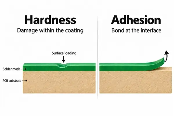
Pencil hardness measures resistance to local mechanical damage; adhesion measures how well the coating attaches to the surface below. A hard film can be poorly bonded, and a well-bonded film can fall below the required pencil grade. Adhesion testing has its own specified preparation, test arrangement, exposure conditions and acceptance criteria. Keep the results separate in the inspection record, even when both tests apply to one lot.
For practical interpretation, 2B is softer than HB, and 9H does not mean Mohs hardness 9: the pencil and mineral scales are unrelated. A paint-panel result doesn’t qualify a PCB mask unless the material, substrate, conditioning and acceptance requirements match the board application. The governing method should come from the controlled revision named in the purchase specification; an informal summary can’t replace it.
The useful result is the one another inspector can reproduce: a traceable sample, controlled cure and setup, a clearly defined damage endpoint and a grade tied to the applicable method. That record makes a hardness change a workable process signal while keeping it distinct from adhesion and other coating properties.