Pickering 41-621 and 43-621 Waveform Generators Put Four Outputs in One PXI Slot
- Nidhi Agarwal
- 522 reads
Pickering’s PXI and PXIe modules offer up to four coordinated waveform outputs in one 3U slot for sensor simulation and automated test.
Test-system capacity can become a practical constraint when a setup needs several synchronized stimulus signals. Pickering Interfaces’ 41-621 PXI and 43-621 PXIe arbitrary waveform generators address that problem by providing up to four separate electrical signal outputs in a single 3U slot. The modules are aimed at avionics functional testing, full authority digital engine control (FADEC) testing, multi-channel sensor simulation and upgrades to legacy automated test equipment.

More outputs from one slot
The main design point is channel density. In the same amount of rack space occupied by a two-channel product, Pickering says its four-channel PXIe model can provide four signal outputs. That lets a test-system designer generate twice as many signals without adding slots, according to the company. Pickering also says its modules provide more outputs per slot than competing products operating above 20MHz.

For systems with limited PXI or PXIe capacity, a slot saved can preserve room for other instruments or interface modules. It can also reduce the pressure to expand a chassis when a test setup grows from a small number of signal sources to several simultaneous sensor inputs. The benefit depends on the required channel count and on whether the generator’s capabilities match the signals and timing the test needs; the announcement doesn’t give further performance specifications or compatibility details.
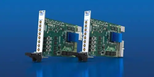
Pickering offers the family in two-channel and four-channel versions, with a choice of PXI or PXIe platform. The 41-621 is the PXI model, while the 43-621 is the PXIe model. That choice gives engineers a way to consider channel density alongside the platform already used in a test rack. The company describes the modules as suitable for both new systems and legacy ATE upgrades.

Signal types and coordinated stimulus
The generators can produce amplitude modulation (AM), frequency modulation (FM), frequency-shift keying (FSK), phase-shift keying (PSK) and pulse-width modulation (PWM), according to Pickering. These signal formats give test engineers options for exercising electronic devices with different kinds of electrical stimulus. The stated use cases include sensor simulation, where several channels may need to represent signals arriving at different points in a system.

Pickering says the channels can produce signals at precisely coordinated times and work together. That matters when a test depends on relationships between inputs, rather than on checking each signal in isolation. With multiple outputs available in one module, the system can deliver several related stimuli while using fewer chassis slots. The announcement doesn’t specify timing accuracy, channel-to-channel phase performance, output ranges or waveform memory, so those details would need to be checked against the intended test requirements.
For avionics and FADEC work, the stated purpose is functional testing: the generator supplies electrical signals that let a test system exercise or simulate inputs to equipment under test. The article does not provide particular test procedures or claim certification for the modules. Engineers planning an integration will still need to match the chosen model and signal configuration to their system’s required stimulus, interfaces and test setup.

Cost claim and application fit
Pickering estimates that its four-channel version costs approximately 40% less per signal output than competing solutions. That is a manufacturer estimate, and no comparison products or pricing basis are identified in the announcement. It should therefore be treated as a claim to assess against a specific system bill of materials, including the number of channels needed and the cost of any alternative modules.

Tom Sarfi, Product Line Manager at Pickering, said engineers need to reproduce more complex signals while keeping systems compact, affordable and supportable. He described the added channels as a way to reduce system footprint and cost without sacrificing stimulus flexibility, and said the modules are intended to support new test systems and legacy ATE upgrades.
The practical attraction is clear: four outputs in one 3U slot could simplify a dense stimulus setup and leave more chassis capacity for other test functions. The strongest case will be where a system needs multiple coordinated signals and can use the stated modulation formats. Before selecting a model, engineers will need the detailed specifications and integration information that determine whether its outputs meet the application’s signal, timing and platform requirements.