3D-Printed Hoverboard Prototype Uses Spinning Halbach Magnet Rotors to Levitate Over Copper
- Muskan Bhatia
- 737 reads
Jake Rogers’ battery-powered prototype hovers above copper using counter-rotating rotors with N52 magnets, though it still needs help staying level.
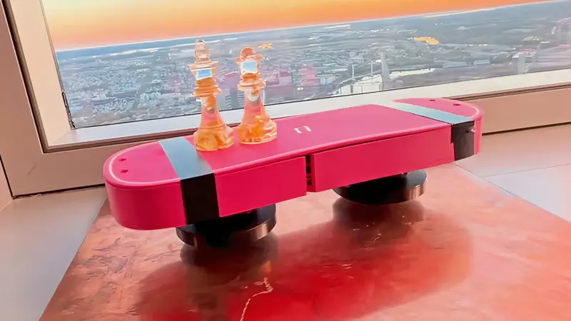
A small copper plate is enough to make Jake Rogers’ battery-powered prototype hover, but keeping the board level remains a work in progress. Its lift comes from two counter-rotating rotors carrying neodymium magnets in a Halbach arrangement. The setup gives Rogers a compact, untethered demonstration of magnetic levitation that needs a conductive surface beneath it.
Concentrating the magnetic field downward
Each custom 3D-printed rotor carries twelve N52 neodymium magnets arranged in a Halbach configuration. The magnets’ orientation concentrates the stronger side of the field downward while leaving a weaker field above the rotor. That directional field is central to the design: the board is intended to interact with the copper plate below it, rather than simply suspend itself over any surface.
The completed board packages the two rotors, two batteries, electronic speed controllers identified as ESP2, and a voltage converter inside a soft pink casing made from Polymaker filament. The motors spin in opposite directions. That choice also addresses a mechanical problem from early tests: a single spinning rotor applies reaction torque to its frame, tending to twist the whole assembly.
Rogers initially tested one motor on a lightweight frame. The exposed wiring and the motor’s torque made the assembly unstable and caused it to rotate unpredictably. Adding a second motor spinning the other way helped balance the torque, but the device then flipped during testing. Sorting out the wiring resolved that issue and allowed him to focus on the rotor and power-system design.
Rotor retention shaped the magnet count
The first rotors held sixteen magnets apiece. At operating speed, centrifugal force pushed the magnets outward, creating a risk that they would escape their positions. Rogers reduced the count to twelve per rotor. The source reports that this cut the outward force by around 40% while maintaining the same speed. That change reflects a practical trade-off in a high-speed rotor: the magnetic layout has to generate useful lift while the printed structure keeps its magnets contained.
The final redesign also changed the board’s power and mass layout. Rogers removed dead batteries that had been used to balance an earlier chassis and placed live 3S battery packs between the motors. The pack can supply 22.2 volts when powered on. With the batteries aboard, the prototype no longer depended on a tether for power and could move over the copper plate under its own power.
That untethered operation is a meaningful step for the prototype, but it doesn’t make the board a rideable device. During the demonstration, it remained unsteady and needed assistance to stay level. The experiment shows lift and movement over a suitable conductive surface; it doesn’t establish controlled, stable flight or practical passenger support.
Lift estimates come with test limitations
Rogers used a sensor on the device and simulations to estimate the forces involved. His calculations put the force on a 3.84-gram magnet at about 61 newtons when it was rotating at 8,000 rpm. For an entire rotor, he estimated 941 grams-force at 3,000 rpm with a 5 mm gap. These figures describe different conditions and quantities, so they shouldn’t be treated as directly interchangeable measures of board lift.
Rogers also cautioned against relying on the simulation-based estimates. The prototype rattled vigorously while hovering, making its behavior difficult to characterize cleanly. The reported values therefore offer a preliminary picture of the magnetic forces, rather than a settled performance result for a stable board. A steadier test setup would be needed to assess how consistently the rotor system produces lift across a defined gap and operating speed.
The copper plate is part of the operating principle, which limits where this design can work. It isn’t a free-moving hoverboard that can cross ordinary floors: its levitation depends on interaction with a conductive surface. That requirement is a defining engineering constraint for any larger version, alongside rotor stability, battery placement, magnet retention and control of the board’s attitude.
Next steps focus on scale and control
Rogers has said he wants to develop a full-size ride-on board called HALO-1, which would also require a conductive surface. Before pursuing that larger build, he plans to try a pocket-sized fingerboard. The smaller project offers a way to continue exploring the same basic arrangement at a scale where the rotor packaging and levitation behavior can be examined without claiming that the present prototype is ready to carry a rider.
For now, the prototype’s clearest result is that a compact battery-powered assembly can levitate and move above copper using spinning Halbach magnet rotors. The next engineering challenge is making that motion stable and repeatable, while keeping the magnets secure and the power system integrated into the board. Until those pieces are demonstrated together, HALO-1 remains a proposed direction rather than a ride-on machine.
===